Revolute joint: Difference between revisions
→top: missing comma; nonsense number |
Switched the initial starting images to align with the wording of the caption for clarity. "with and without shoulders" could imply that the first image was the one with shoulders, which was not the case at the time. |
||
| Line 2: | Line 2: | ||
{{multiple image |
{{multiple image |
||
| width = 150 |
| width = 150 |
||
| image1 = |
| image1 = Revolute_Pin_Joint.png |
||
| alt1 = Revolute joint cutaway view |
| alt1 = Revolute joint with shoulders cutaway view |
||
| image2 = |
| image2 = Revolute joint.svg |
||
| alt2 = Revolute joint |
| alt2 = Revolute joint cutaway view |
||
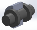
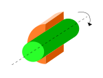
| footer = Revolute joint with and without shoulders, cutaway views |
| footer = Revolute joint with and without shoulders, cutaway views |
||
}} |
}} |
||
Latest revision as of 11:41, 5 July 2024
A revolute joint (also called pin joint or hinge joint) is a one-degree-of-freedom kinematic pair used frequently in mechanisms and machines.[1] The joint constrains the motion of two bodies to pure rotation along a common axis. The joint does not allow translation, or sliding linear motion, a constraint not shown in the diagram. Almost all assemblies of multiple moving bodies include revolute joints in their designs. Revolute joints are used in numerous applications such as door hinges, mechanisms, and other uni-axial rotation devices.[2]
A revolute joint is usually made by a pin or knuckle joint, through a rotary bearing. It enforces a cylindrical contact area, which makes it a lower kinematic pair, also called a full joint. However, If there is any clearance between the pin and hole (as there must be for motion), so-called surface contact in the pin joint actually becomes line contact.[3]
The contact between the inner and outer cylindrical surfaces is usually assumed to be frictionless. But some use simplified models assume linear viscous damping in the form , where T is the friction torque, ω is the relative angular velocity, and B is the friction constant. Some more complex models take stiction and stribeck effect into consideration.[4]

See also
[edit]References
[edit]- ^ Norton, Robert L. (2008). "2". Design of Machinery (4th ed.). Boston, MA: McGraw Hill Higher Education. p. 33. ISBN 978-0-07-312158-1.
- ^ Robotics Research Group. "Joint Types". University of Texas at Austin. Archived from the original on 2009-03-11. Retrieved 2009-02-04.
- ^ Norton, Robert L. Design of machinery: an introduction to the synthesis and analysis of mechanisms and machines. Boston: McGraw-Hill Higher Education, 2004. p. 31.
- ^ Moore, Jacobs. "Bearing Friction". Mechanics Map. Retrieved June 6, 2020.


