Earth–Moon–Earth communication: Difference between revisions
Moonandback (talk | contribs) Project Diana was the first purpose-driven effort specifically designed to explore the potential of EME communication for space exploration and defense, as opposed to incidental observations spilling out of efforts to develop equipment for detecting near-ground targets. |
→History: The source is the CQ DL article, not the original Der Seewart article. It is also wrong to claim Ing. is the first name as "Dr. Ing." is together, meaning "Doktoringenieur", i.e. Doctor of Engineering in German. |
||
| (32 intermediate revisions by 20 users not shown) | |||
| Line 1: | Line 1: | ||
{{short description|Radio communications technique}} |
|||
'''Earth–Moon–Earth communication''' ('''EME'''), also known as '''Moon bounce''', is a [[radio communications]] technique that relies on the [[Radio propagation|propagation]] of [[radio waves]] from an [[Earth]]-based [[transmitter]] directed via [[reflection (physics)|reflection]] from the surface of the [[Moon]] back to an Earth-based [[receiver (radio)|receiver]]. |
'''Earth–Moon–Earth communication''' ('''EME'''), also known as '''Moon bounce''', is a [[radio communications]] technique that relies on the [[Radio propagation|propagation]] of [[radio waves]] from an [[Earth]]-based [[transmitter]] directed via [[reflection (physics)|reflection]] from the surface of the [[Moon]] back to an Earth-based [[receiver (radio)|receiver]]. |
||
== History == |
== History == |
||
The use of the Moon as a [[Passivity (engineering)|passive]] communications [[satellite]] was proposed by [[John Bray (communications engineer)|W.J. Bray]] of the British [[General Post Office]] in 1940. It was calculated that with the available [[microwave transmission]] powers and [[Low-noise amplifier|low |
The use of the Moon as a [[Passivity (engineering)|passive]] communications [[satellite]] was proposed by [[John Bray (communications engineer)|W.J. Bray]] of the British [[General Post Office]] in 1940. It was calculated that with the available [[microwave transmission]] powers and [[Low-noise amplifier|low-noise receivers]], it would be possible to beam [[microwave]] [[Radio signal|signal]]s up from Earth and [[reflection (physics)|reflect]] them off the Moon. It was thought that at least one voice [[Channel (communications)|channel]] would be possible.<ref>{{cite book |
||
| last = Pether |
| last = Pether |
||
| first = John |
| first = John |
||
| Line 11: | Line 12: | ||
| page = 25 }}</ref> |
| page = 25 }}</ref> |
||
| ⚫ | Radar reflections off the moon were received and recognized as such in 1943 during German experiments with radio measurement equipment, as reported by Dr. Ing. W. Stepp in ''Der Seewart'' magazine. Stepp noted a "perturbation", which "appeared, had a duration of several impulses, and larger impulse strength than the strongest nearby targets. It didn't appear until about two seconds after switching on the transmitter and disappeared (pulsatingly) correspondingly later after switching it off. But the rest of the echo image appeared and disappeared at the instance of switching the transmitter on/off. The 'perturbation' only occurred when the antenna was aimed to the east, and it disappeared immediately upon a major change of direction, but reappeared only about two seconds after rotating back to the original direction. Apparently we had detected the rising moon behind the clouds with the equipment. It explained the gradual disappearance of the impulses by the reflecting body slowly moving out of the strongly focussed, horizontally aimed beam, as it rises above the horizon."<ref>{{cite web |
||
In the English literature, which has also become known in German-speaking countries, it was always assumed that the first EME was done in the USA. But according to reports by Dr. Ing. W. Stepp in the "Der Seewart" magazine, it seems that already in 1943, during experiments with radio measurement equipment, (radar) reflections of the moon were received and recognized as such. Since so far nothing was published about this in cq-DL, the report by Dr. Stepp is presented here as a preamble to the activities of German VHF amateurs. |
|||
| ⚫ | |||
|title= cq-DL 7/79, p. 328 |
|||
|author= DK2ZF |
|||
|translator-last= de Boer |
|||
|translator-first= Pieter-Tjerk |
|||
|website= PA3FWM's homepage |
|||
| ⚫ | |||
|quote=}}</ref> |
|||
| ⚫ | It was not until the close of [[World War II]], however, that techniques specifically intended for the purpose of bouncing radar waves off the moon to demonstrate their potential use in defense, communication, and [[radar astronomy]] were developed. The first successful attempt was carried out at [[Fort Monmouth]], New Jersey, on January 10, 1946, by a group code-named [[Project Diana]], headed by [[John H. DeWitt]].<ref>{{cite book |
||
Dr. Stepp writes: "In 1943 Telefunken had taken up the task of developing radio measuring equipment for detecting and surveying targets near ground -- ships, low-flying aircraft, cars -- with as large a range as possible. |
|||
The task of locating near-ground targets especially required, besides high power and high receiver sensitivity, wavelengths as short as possible. A setup with the following parameters was developed, matching the possibilities of that time: |
|||
Transmitter impulse power 120 kW ; |
|||
Impulse duration 1.5 µs ; |
|||
Wavelength 53 cm, about 564 MHz ; |
|||
RX sensitivity 12 kTo ; |
|||
Antenna surface 45 m2 ; |
|||
Polarization horizontal ; |
|||
Number of dipoles 8 per row horiz., 80 per column vert. |
|||
[Translator's note: presumably the 12 kTo sensitivity means the receiver's own noise is 12 times thermal noise (Boltzmann's constant k times absolute temperature To), which is equivalent to a noise figure of 11 dB.] |
|||
The antenna could be rotated around its vertical axis. It was strongly focused vertically with the first nulls 1.3° away from the horizontal main lobe. |
|||
The device was given the name "Würzmann". For testing, the system was set up in late 1943 on the Bakenberg on the south of the island of Rügen. |
|||
The measurement results confirmed the calculated ranges: ships of average size were detected up to the horizon, about 50 km, and airplanes till 1000 m high up to distances of about 100 km. But with favorable weather conditions the system detected targets in the harbour of Gdansk and the Gulf of Finland. |
|||
After the first tests I assigned Willi Thiel, one of the very competent engineers, to take care of the equipment on his own and continuously perform observations. Some weeks later I again travelled to the Rügen island for experiments near Göhren. On the last day of the experiments, just a few hours before leaving back to Berlin, I visited the Bakenberg again. The sky was very dull, the night very dark. On the way to the Bakenberg W. Thiel reported about a "strange equipment perturbation", which he had observed on the previous day at approximately the same time, but of which he had not been able to find the cause; however, it had become less after about two hours despite him not fixing it, and in the end had disappeared completely. |
|||
| ⚫ | |||
http://pa3fwm.nl/technotes/annex/cqdl-7-79-eme.html |
|||
| ⚫ | It was not until the close of [[World War II]], however, that techniques specifically intended for the purpose of bouncing radar waves off the moon to demonstrate their potential use in defense, communication, and radar astronomy were developed. The first successful attempt was carried out at [[Fort Monmouth]], New Jersey on January 10, 1946 by a group code-named [[Project Diana]], headed by [[John H. DeWitt]].<ref>{{cite book |
||
| last = Butrica |
| last = Butrica |
||
| first = Andrew J. |
| first = Andrew J. |
||
| Line 43: | Line 29: | ||
| date = 1996 |
| date = 1996 |
||
| url = https://history.nasa.gov/SP-4218/ch1.htm |
| url = https://history.nasa.gov/SP-4218/ch1.htm |
||
| |
|archive-url=https://web.archive.org/web/20070823124845/https://history.nasa.gov/SP-4218/ch1.htm|archive-date=2007-08-23}}</ref> It was followed less than a month later, on February 6, 1946, by a second successful attempt, by a Hungarian group led by [[Zoltán Lajos Bay|Zoltán Bay]].<ref>{{cite web |
||
| url = http://www.omikk.bme.hu/archivum/angol/htm/bay_z.htm |
| url = http://www.omikk.bme.hu/archivum/angol/htm/bay_z.htm |
||
| title = Bay, Zoltán |
| title = Bay, Zoltán |
||
| last = |
|||
| first = |
|||
| ⚫ | |||
| website = omikk.bme.hu |
| website = omikk.bme.hu |
||
| publisher = OMIKK |
| publisher = OMIKK |
||
| access-date = 2017-01-13 |
| access-date = 2017-01-13 |
||
}}</ref> The [[Communication Moon Relay]] project that followed led to more practical uses, including a [[teleprinter|teletype]] link between the naval base at [[Pearl Harbor]], [[Hawaii]] and [[United States Navy]] headquarters in [[Washington, D.C.]] In the days before [[communications satellite]]s, a link free of the [[wikt:vagary|vagaries]] of [[skywave|ionospheric propagation]] was revolutionary. |
|||
The development of [[communication satellite]]s in the 1960s made this technique obsolete. |
The development of [[communication satellite]]s in the 1960s made this technique obsolete. However, [[radio amateur]]s took up EME communication as a hobby; the first [[amateur radio]] moonbounce communication took place in 1953, and amateurs worldwide still use the technique. Composer [[Pauline Oliveros]] used moonbounce in her 1987 work ''Echoes from the Moon,''<ref>{{Cite journal |last=Barrett |first=G Douglas |date=2021 |title=Deep (Space) Listening: Posthuman Moonbounce in Pauline Oliveros's Echoes from the Moon |url=https://muse.jhu.edu/article/810823 |journal=Discourse |volume=43 |issue=3 |pages=321 |doi=10.13110/discourse.43.3.0321}}</ref> and in 2024 German musician [[Hainbach (musician)|Hainbach]] experimented with moonbounce and created an [[audio plug-in]] to reproduce the effect.<ref>{{Cite web |last=Fabio |first=Adam |date=2024-08-11 |title=Moonbounce Music |url=https://hackaday.com/2024/08/11/moonbounce-music/ |access-date=2024-08-19 |website=Hackaday |language=en-US}}</ref> |
||
== Current EME communications == |
== Current EME communications == |
||
| Line 67: | Line 50: | ||
Amateur frequency bands from 50 MHz to 47 GHz have been used successfully, but most EME communications are on the [[2-meter band|2 meter]], [[70-centimeter band|70-centimeter]], or [[23-centimeter band|23-centimeter]] bands. Common modulation modes are [[continuous wave]] with Morse code, digital ([[WSJT (amateur radio software)|JT65]]) and when the link budgets allow, voice. |
Amateur frequency bands from 50 MHz to 47 GHz have been used successfully, but most EME communications are on the [[2-meter band|2 meter]], [[70-centimeter band|70-centimeter]], or [[23-centimeter band|23-centimeter]] bands. Common modulation modes are [[continuous wave]] with Morse code, digital ([[WSJT (amateur radio software)|JT65]]) and when the link budgets allow, voice. |
||
Recent advances in [[digital signal processing]] have allowed EME contacts, admittedly with low data rate, to take place with powers in the order of [[Orders of magnitude (power)|100 |
Recent advances in [[digital signal processing]] have allowed EME contacts, admittedly with low data rate, to take place with powers in the order of [[Orders of magnitude (power)|100 watts]] and a single [[Yagi–Uda antenna]]. |
||
World Moon Bounce Day, June 29, 2009, was created by [[Echoes of Apollo]] and celebrated worldwide as an event preceding the 40th [[anniversary]] of the [[Apollo 11]] Moon landing. A highlight of the celebrations was an interview via the Moon with [[Apollo 8]] astronaut [[William Anders|Bill Anders]], who was also part of the backup crew for Apollo 11. The [[University of Tasmania]] in Australia with their 26-meter [[Dish antenna|dish]] were able to bounce a data signal off the surface of the Moon which was received by a large dish in the Netherlands, [[Dwingeloo Radio Observatory]]. The data signal was successfully resolved back to data setting a world record for the lowest power data signal returned from the Moon with a transmit power of 3 milliwatts, about 1,000th of the power of a [[flashlight]] lamp. The second World Moon Bounce Day was April 17, 2010, coinciding with the 40th anniversary of the conclusion of the Apollo 13 mission. |
World Moon Bounce Day, June 29, 2009, was created by [[Echoes of Apollo]] and celebrated worldwide as an event preceding the 40th [[anniversary]] of the [[Apollo 11]] Moon landing. A highlight of the celebrations was an interview via the Moon with [[Apollo 8]] astronaut [[William Anders|Bill Anders]], who was also part of the backup crew for Apollo 11. The [[University of Tasmania]] in Australia with their 26-meter (85') [[Dish antenna|dish]] were able to bounce a data signal off the surface of the Moon which was received by a large dish in the Netherlands, [[Dwingeloo Radio Observatory]]. The data signal was successfully resolved back to data setting a world record for the lowest power data signal returned from the Moon with a transmit power of 3 milliwatts, about 1,000th of the power of a [[flashlight]] lamp. The second World Moon Bounce Day was April 17, 2010, coinciding with the 40th anniversary of the conclusion of the Apollo 13 mission. |
||
In October 2009 media artist Daniela de Paulis proposed to the CAMRAS radio amateur association based at the Dwingeloo Radio Observatory to use Moon bounce for a live image transmission performance. As a result of her proposal, in December 2009 CAMRAS radio operator Jan van Muijlwijk and radio operator Daniel Gautchi made the first image transmission via the Moon using the open source software MMSSTV. De Paulis called the innovative technology "Visual Moonbounce" and since 2010 she has been using it in several of her art projects, including the live performance called OPTICKS, during which digital images are sent to the Moon and back in [[Real-time computing|real time]] and projected live. |
In October 2009 media artist Daniela de Paulis proposed to the CAMRAS radio amateur association based at the Dwingeloo Radio Observatory to use Moon bounce for a live image transmission performance. As a result of her proposal, in December 2009 CAMRAS radio operator Jan van Muijlwijk and radio operator Daniel Gautchi made the first image transmission via the Moon using the open source software MMSSTV. De Paulis called the innovative technology "Visual Moonbounce" and since 2010 she has been using it in several of her art projects, including the live performance called OPTICKS, during which digital images are sent to the Moon and back in [[Real-time computing|real time]] and projected live. |
||
| Line 75: | Line 58: | ||
== Echo delay and time spread == |
== Echo delay and time spread == |
||
[[Radio waves]] [[Radio propagation|propagate]] in vacuum at the [[speed of light]] ''c'', exactly 299,792,458 m/s. Propagation time to the Moon and back ranges from 2.4 to 2.7 |
[[Radio waves]] [[Radio propagation|propagate]] in vacuum at the [[speed of light]] ''c'', exactly 299,792,458 m/s. Propagation time to the Moon and back ranges from 2.4 to 2.7 seconds, with an average of 2.56 seconds (the average distance from Earth to the Moon is 384,400 km). |
||
The Moon is nearly spherical, and its radius corresponds to about 5.8 milliseconds of wave travel time. The trailing parts of an echo, reflected from [[Moon#Surface |
The Moon is nearly spherical, and its radius corresponds to about 5.8 milliseconds of wave travel time. The trailing parts of an echo, reflected from [[Moon#Surface features|irregular surface features]] near the edge of the lunar disk, are delayed from the leading edge by as much as twice this value. |
||
Most of the Moon's surface appears relatively smooth at the typical microwave wavelengths used for amateur EME. Most amateurs do EME contacts below 6 GHz, and differences in the moon's reflectivity are somewhat hard to discern above 1 GHz. |
Most of the Moon's surface appears relatively smooth at the typical microwave wavelengths used for amateur EME. Most amateurs do EME contacts below 6 GHz, and differences in the moon's reflectivity are somewhat hard to discern above 1 GHz. |
||
| Line 87: | Line 70: | ||
At shorter wavelengths the lunar surface appears increasingly rough, so reflections at 10 GHz and above contain a significant [[Diffuse reflection|diffuse]] component as well as a quasi-specular component. The diffuse component is depolarized, and can be viewed as a source of low level system noise. Significant portions of the diffused component arise from regions farther out toward the lunar rim. The [[median]] time spread can then be as much as several milliseconds. In all practical cases, however, time spreading is small enough that it does not cause significant smearing of [[Continuous wave|CW]] keying or [[intersymbol interference]] in the slowly keyed [[modulation]]s commonly used for digital EME. The diffused component may appear as significant noise at higher message data rates. |
At shorter wavelengths the lunar surface appears increasingly rough, so reflections at 10 GHz and above contain a significant [[Diffuse reflection|diffuse]] component as well as a quasi-specular component. The diffuse component is depolarized, and can be viewed as a source of low level system noise. Significant portions of the diffused component arise from regions farther out toward the lunar rim. The [[median]] time spread can then be as much as several milliseconds. In all practical cases, however, time spreading is small enough that it does not cause significant smearing of [[Continuous wave|CW]] keying or [[intersymbol interference]] in the slowly keyed [[modulation]]s commonly used for digital EME. The diffused component may appear as significant noise at higher message data rates. |
||
EME time spreading does have one very significant effect. Signal components reflected from different parts of the lunar surface travel different distances and arrive at Earth with random phase relationships. As the relative geometry of the |
EME time spreading does have one very significant effect. Signal components reflected from different parts of the lunar surface travel different distances and arrive at Earth with random phase relationships. As the relative geometry of the transmitting station, receiving station and reflecting lunar surface changes, signal components sometimes add and sometimes cancel, depending on their [[Phase (waves)|phase]] relationship, creating large amplitude fluctuations in the received signal. These "libration fading" amplitude variations are well correlated over the [[coherence bandwidth]] (typically a few kHz). The libration [[fading]] components are related to the time spread of reflected signals. |
||
transmitting station, receiving station and reflecting lunar surface changes, signal components may sometimes add and sometimes cancel. |
|||
The dynamic addition and cancellation will create large amplitude fluctuations. These amplitude variations are referred to as "libration fading". These amplitude variations will be well correlated over the coherence [[Bandwidth (signal processing)|bandwidth]] (typically a few kHz). The libration [[fading]] components are related to the time spread of reflected signals. |
|||
== Modulation types and frequencies for EME == |
== Modulation types and frequencies for EME == |
||
| Line 96: | Line 76: | ||
[[Very high frequency|VHF]] |
[[Very high frequency|VHF]] |
||
* [[Continuous wave|CW]] |
* [[Continuous wave|CW]] |
||
* [[WSJT (amateur radio software)|JT65A |
* [[WSJT (amateur radio software)|JT65A, JT65B, Q65]] |
||
[[Ultra high frequency|UHF]] |
[[Ultra high frequency|UHF]] |
||
* [[Continuous wave|CW]] |
* [[Continuous wave|CW]] |
||
* [[WSJT (amateur radio software)| |
* [[WSJT (amateur radio software)|JT65, Q65]] |
||
* [[Single-sideband modulation|SSB]] |
* [[Single-sideband modulation|SSB]] |
||
| Line 106: | Line 86: | ||
* [[Continuous wave|CW]] |
* [[Continuous wave|CW]] |
||
* [[Single-sideband modulation|SSB]] |
* [[Single-sideband modulation|SSB]] |
||
* [[WSJT (amateur radio software)| |
* [[WSJT (amateur radio software)|Q65]] |
||
== Other factors influencing EME communications == |
== Other factors influencing EME communications == |
||
[[Doppler effect]] at 144 MHz band is 300 Hz at moonrise or moonset. The doppler offset |
[[Doppler effect]] at 144 MHz band is 300 Hz at moonrise or moonset. The doppler offset reduces to around zero when the Moon is overhead. At other frequencies other doppler offsets will exist. At moonrise, returned signals will be shifted approximately 300 Hz higher in frequency. As the Moon traverses the sky to a point due south or due north, the Doppler effect approaches zero. By Moonset, they are shifted 300 Hz lower. Doppler effects cause many problems when tuning into, and locking onto, signals from the Moon. |
||
[[Polarization (waves)|Polarization]] effects can reduce the strength of received signals. |
[[Polarization (waves)|Polarization]] effects can reduce the strength of received signals. One component is the geometrical alignment of the transmitting and receiving antennas. Many antennas produce a preferred plane of polarization. Transmitting and receiving station antennas may not be aligned from the perspective of an observer on the moon. This component is fixed by the alignment of the antennas and stations may include a facility to rotate antennas to adjust polarization. Another component is [[Faraday rotation]] on the Earth-Moon-Earth path. The plane of polarization of radio waves rotates as they pass through ionized layers of the Earth's atmosphere. This effect is more pronounced at lower VHF frequencies and becomes less significant at 1296 MHz and above. Some of the polarization mismatch loss can be reduced by using a larger antenna array (more Yagi elements or a larger dish).<ref>Larry Wolfgang, Charles Hutchinson, (ed), ''The ARRL |Handbook for Radio Amateurs, Sixty Eighth Edition '', American Radio Relay League, 1990 {{ISBN|0-87259-168-9}}, pages 23-34, 23-25,</ref> |
||
== Gallery == |
== Gallery == |
||
<gallery perrow=3 widths=200px heights=200px> |
<gallery perrow="3" widths="200px" heights="200px"> |
||
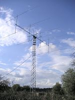
Image:EA6VQ_EME.jpg|An array of |
Image:EA6VQ_EME.jpg|An array of eight Yagi antennas for 144 MHz EME at EA6VQ, Balearic Islands, Spain |
||
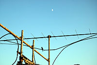
Image:144MHz_EME.jpg|A part of 144 MHz EME antenna array at WA6PY in California, |
Image:144MHz_EME.jpg|A part of 144 MHz EME antenna array at WA6PY in California, U.S. |
||
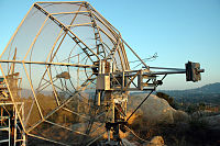
Image:EME_dish.jpg|A dish antenna for microwave EME work at WA6PY, California, |
Image:EME_dish.jpg|A dish antenna for microwave EME work at WA6PY, California, U.S. |
||
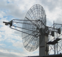
Image:I2FZX_UHF_EME_Antenna.png|A dish antenna for UHF EME at I2FZX, Milan, Italy |
Image:I2FZX_UHF_EME_Antenna.png|A dish antenna for UHF EME at I2FZX, Milan, Italy |
||
File:SM3PWM EME Antenna.jpg|Amateur |
File:SM3PWM EME Antenna.jpg|Amateur radio antenna array used for Earth–Moon–Earth communication on 144 MHz. Location Kilafors in central Sweden. |
||
File:SM5BSZ EME Antenna.jpg|Amateur |
File:SM5BSZ EME Antenna.jpg|Amateur radio antenna array used for Earth–Moon–Earth communication on 144 MHz. Location Jäder, central Sweden. |
||
File:SM7BAE EME Antenna.jpg|Amateur |
File:SM7BAE EME Antenna.jpg|Amateur radio antenna array used for Earth–Moon–Earth communication on 144 MHz. Location Staffanstorp, southern Sweden. |
||
</gallery> |
</gallery> |
||
| Line 131: | Line 111: | ||
*[[Meteor burst communications]] |
*[[Meteor burst communications]] |
||
*[[Passive repeater]] |
*[[Passive repeater]] |
||
*[[Radar#Radar equation|Radar equation]] |
*[[Radar#Radar range equation|Radar equation]] |
||
*[[Unified S-band]] |
*[[Unified S-band]] |
||
==References== |
==References== |
||
| Line 138: | Line 118: | ||
== External links == |
== External links == |
||
* [https://history.nasa.gov/SP-4217/ch2.htm NASA, ''Beyond the Ionosphere: the development of satellite communications''] |
* [https://history.nasa.gov/SP-4217/ch2.htm NASA, ''Beyond the Ionosphere: the development of satellite communications''] |
||
| ⚫ | |||
* http://www.k5rmg.org/tech/EME.html (another calculator) |
|||
| ⚫ | |||
* http://www.camras.nl site of CAMRAS radio amateurs association at Dwingeloo radio telescope |
* http://www.camras.nl site of CAMRAS radio amateurs association at Dwingeloo radio telescope |
||
* http://www.opticks.info |
* http://www.opticks.info |
||
| Line 151: | Line 130: | ||
}} |
}} |
||
* https://www.mitpressjournals.org/doi/abs/10.1162/LEON_a_01098 |
* https://www.mitpressjournals.org/doi/abs/10.1162/LEON_a_01098 |
||
| ⚫ | |||
{{RF Propagation Navbox}} |
{{RF Propagation Navbox}} |
||
| Line 157: | Line 135: | ||
{{DEFAULTSORT:Earth-Moon-Earth communication}} |
{{DEFAULTSORT:Earth-Moon-Earth communication}} |
||
[[Category:Radio frequency propagation]] |
[[Category:Radio frequency propagation]] |
||
[[Category: |
[[Category:Lunar science]] |
||
Latest revision as of 13:42, 26 August 2024
Earth–Moon–Earth communication (EME), also known as Moon bounce, is a radio communications technique that relies on the propagation of radio waves from an Earth-based transmitter directed via reflection from the surface of the Moon back to an Earth-based receiver.
History
[edit]The use of the Moon as a passive communications satellite was proposed by W.J. Bray of the British General Post Office in 1940. It was calculated that with the available microwave transmission powers and low-noise receivers, it would be possible to beam microwave signals up from Earth and reflect them off the Moon. It was thought that at least one voice channel would be possible.[1]
Radar reflections off the moon were received and recognized as such in 1943 during German experiments with radio measurement equipment, as reported by Dr. Ing. W. Stepp in Der Seewart magazine. Stepp noted a "perturbation", which "appeared, had a duration of several impulses, and larger impulse strength than the strongest nearby targets. It didn't appear until about two seconds after switching on the transmitter and disappeared (pulsatingly) correspondingly later after switching it off. But the rest of the echo image appeared and disappeared at the instance of switching the transmitter on/off. The 'perturbation' only occurred when the antenna was aimed to the east, and it disappeared immediately upon a major change of direction, but reappeared only about two seconds after rotating back to the original direction. Apparently we had detected the rising moon behind the clouds with the equipment. It explained the gradual disappearance of the impulses by the reflecting body slowly moving out of the strongly focussed, horizontally aimed beam, as it rises above the horizon."[2]
It was not until the close of World War II, however, that techniques specifically intended for the purpose of bouncing radar waves off the moon to demonstrate their potential use in defense, communication, and radar astronomy were developed. The first successful attempt was carried out at Fort Monmouth, New Jersey, on January 10, 1946, by a group code-named Project Diana, headed by John H. DeWitt.[3] It was followed less than a month later, on February 6, 1946, by a second successful attempt, by a Hungarian group led by Zoltán Bay.[4] The Communication Moon Relay project that followed led to more practical uses, including a teletype link between the naval base at Pearl Harbor, Hawaii and United States Navy headquarters in Washington, D.C. In the days before communications satellites, a link free of the vagaries of ionospheric propagation was revolutionary.
The development of communication satellites in the 1960s made this technique obsolete. However, radio amateurs took up EME communication as a hobby; the first amateur radio moonbounce communication took place in 1953, and amateurs worldwide still use the technique. Composer Pauline Oliveros used moonbounce in her 1987 work Echoes from the Moon,[5] and in 2024 German musician Hainbach experimented with moonbounce and created an audio plug-in to reproduce the effect.[6]
Current EME communications
[edit]Amateur radio (ham) operators utilize EME for two-way communications. EME presents significant challenges to amateur operators interested in weak signal communication. EME provides the longest communications path any two stations on Earth can use.
Amateur frequency bands from 50 MHz to 47 GHz have been used successfully, but most EME communications are on the 2 meter, 70-centimeter, or 23-centimeter bands. Common modulation modes are continuous wave with Morse code, digital (JT65) and when the link budgets allow, voice.
Recent advances in digital signal processing have allowed EME contacts, admittedly with low data rate, to take place with powers in the order of 100 watts and a single Yagi–Uda antenna.
World Moon Bounce Day, June 29, 2009, was created by Echoes of Apollo and celebrated worldwide as an event preceding the 40th anniversary of the Apollo 11 Moon landing. A highlight of the celebrations was an interview via the Moon with Apollo 8 astronaut Bill Anders, who was also part of the backup crew for Apollo 11. The University of Tasmania in Australia with their 26-meter (85') dish were able to bounce a data signal off the surface of the Moon which was received by a large dish in the Netherlands, Dwingeloo Radio Observatory. The data signal was successfully resolved back to data setting a world record for the lowest power data signal returned from the Moon with a transmit power of 3 milliwatts, about 1,000th of the power of a flashlight lamp. The second World Moon Bounce Day was April 17, 2010, coinciding with the 40th anniversary of the conclusion of the Apollo 13 mission.
In October 2009 media artist Daniela de Paulis proposed to the CAMRAS radio amateur association based at the Dwingeloo Radio Observatory to use Moon bounce for a live image transmission performance. As a result of her proposal, in December 2009 CAMRAS radio operator Jan van Muijlwijk and radio operator Daniel Gautchi made the first image transmission via the Moon using the open source software MMSSTV. De Paulis called the innovative technology "Visual Moonbounce" and since 2010 she has been using it in several of her art projects, including the live performance called OPTICKS, during which digital images are sent to the Moon and back in real time and projected live.
Echo delay and time spread
[edit]Radio waves propagate in vacuum at the speed of light c, exactly 299,792,458 m/s. Propagation time to the Moon and back ranges from 2.4 to 2.7 seconds, with an average of 2.56 seconds (the average distance from Earth to the Moon is 384,400 km).
The Moon is nearly spherical, and its radius corresponds to about 5.8 milliseconds of wave travel time. The trailing parts of an echo, reflected from irregular surface features near the edge of the lunar disk, are delayed from the leading edge by as much as twice this value.
Most of the Moon's surface appears relatively smooth at the typical microwave wavelengths used for amateur EME. Most amateurs do EME contacts below 6 GHz, and differences in the moon's reflectivity are somewhat hard to discern above 1 GHz.
Lunar reflections are by nature quasi-specular (like those from a shiny ball bearing). The power useful for communication is mostly reflected from a small region near the center of the disk. The effective time spread of an echo amounts to no more than 0.1 ms.
Antenna polarization for EME stations must consider that reflection from a smooth surface preserves linear polarization but reverses the sense of circular polarizations.
At shorter wavelengths the lunar surface appears increasingly rough, so reflections at 10 GHz and above contain a significant diffuse component as well as a quasi-specular component. The diffuse component is depolarized, and can be viewed as a source of low level system noise. Significant portions of the diffused component arise from regions farther out toward the lunar rim. The median time spread can then be as much as several milliseconds. In all practical cases, however, time spreading is small enough that it does not cause significant smearing of CW keying or intersymbol interference in the slowly keyed modulations commonly used for digital EME. The diffused component may appear as significant noise at higher message data rates.
EME time spreading does have one very significant effect. Signal components reflected from different parts of the lunar surface travel different distances and arrive at Earth with random phase relationships. As the relative geometry of the transmitting station, receiving station and reflecting lunar surface changes, signal components sometimes add and sometimes cancel, depending on their phase relationship, creating large amplitude fluctuations in the received signal. These "libration fading" amplitude variations are well correlated over the coherence bandwidth (typically a few kHz). The libration fading components are related to the time spread of reflected signals.
Modulation types and frequencies for EME
[edit]Other factors influencing EME communications
[edit]Doppler effect at 144 MHz band is 300 Hz at moonrise or moonset. The doppler offset reduces to around zero when the Moon is overhead. At other frequencies other doppler offsets will exist. At moonrise, returned signals will be shifted approximately 300 Hz higher in frequency. As the Moon traverses the sky to a point due south or due north, the Doppler effect approaches zero. By Moonset, they are shifted 300 Hz lower. Doppler effects cause many problems when tuning into, and locking onto, signals from the Moon.
Polarization effects can reduce the strength of received signals. One component is the geometrical alignment of the transmitting and receiving antennas. Many antennas produce a preferred plane of polarization. Transmitting and receiving station antennas may not be aligned from the perspective of an observer on the moon. This component is fixed by the alignment of the antennas and stations may include a facility to rotate antennas to adjust polarization. Another component is Faraday rotation on the Earth-Moon-Earth path. The plane of polarization of radio waves rotates as they pass through ionized layers of the Earth's atmosphere. This effect is more pronounced at lower VHF frequencies and becomes less significant at 1296 MHz and above. Some of the polarization mismatch loss can be reduced by using a larger antenna array (more Yagi elements or a larger dish).[7]
Gallery
[edit]-
An array of eight Yagi antennas for 144 MHz EME at EA6VQ, Balearic Islands, Spain
-
A part of 144 MHz EME antenna array at WA6PY in California, U.S.
-
A dish antenna for microwave EME work at WA6PY, California, U.S.
-
A dish antenna for UHF EME at I2FZX, Milan, Italy
-
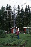
Amateur radio antenna array used for Earth–Moon–Earth communication on 144 MHz. Location Kilafors in central Sweden.
-
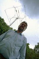
Amateur radio antenna array used for Earth–Moon–Earth communication on 144 MHz. Location Jäder, central Sweden.
-
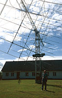
Amateur radio antenna array used for Earth–Moon–Earth communication on 144 MHz. Location Staffanstorp, southern Sweden.
See also
[edit]- Communication Moon Relay
- Information theory
- Lunar Laser Ranging experiment
- Meteor burst communications
- Passive repeater
- Radar equation
- Unified S-band
References
[edit]- ^ Pether, John (1998). The Post Office at War. Bletchley Park Trust. p. 25.
- ^ DK2ZF. "cq-DL 7/79, p. 328". PA3FWM's homepage. Translated by de Boer, Pieter-Tjerk.
{{cite web}}: CS1 maint: numeric names: authors list (link) - ^ Butrica, Andrew J. (1996). To See the Unseen: A History of Planetary Radar Astronomy. NASA. Archived from the original on 2007-08-23.
- ^ "Bay, Zoltán". omikk.bme.hu. OMIKK. Retrieved 2017-01-13.
- ^ Barrett, G Douglas (2021). "Deep (Space) Listening: Posthuman Moonbounce in Pauline Oliveros's Echoes from the Moon". Discourse. 43 (3): 321. doi:10.13110/discourse.43.3.0321.
- ^ Fabio, Adam (2024-08-11). "Moonbounce Music". Hackaday. Retrieved 2024-08-19.
- ^ Larry Wolfgang, Charles Hutchinson, (ed), The ARRL |Handbook for Radio Amateurs, Sixty Eighth Edition , American Radio Relay League, 1990 ISBN 0-87259-168-9, pages 23-34, 23-25,
External links
[edit]- NASA, Beyond the Ionosphere: the development of satellite communications
- https://web.archive.org/web/20071226052052/https://www.df9cy.de/tech-mat/pathloss.htm/ (gives formulas for EME path loss calculation)
- http://www.camras.nl site of CAMRAS radio amateurs association at Dwingeloo radio telescope
- http://www.opticks.info
- https://web.archive.org/web/20100213034553/http://echoesofapollo.com/moon-bounce/ World Moon Bounce Day - Echoes of Apollo
- http://www.wia.org.au/members/armag/2009/august/ Amateur Radio - August 2009 - Wireless Institute of Australia
- http://www.k3pgp.org/uhftveme.htm K3PGP - UHF TV reception via Earth–Moon–Earth communication
- UHF TV carrier reception via moonbounce (EME) at the Wayback Machine (archived 14 March 2019)
- https://www.mitpressjournals.org/doi/abs/10.1162/LEON_a_01098


