HDCI: Difference between revisions
Appearance
Content deleted Content added
No edit summary |
|||
| Line 1: | Line 1: | ||
[[File:HDCI Polycom 2457-29759-010.jpg|thumb|alt=Polycom HDCI Connector]] |
[[File:HDCI Polycom 2457-29759-010.jpg|thumb|alt=Polycom HDCI Connector]] |
||
'''HDCI (High Definition Camera Interface)''' used in Polycom HDX video conferencing systems. It uses a 60-Pin [[Low-force helix]] high-density connector interface. |
'''HDCI (High Definition Camera Interface)''' used in Polycom HDX video conferencing systems. It uses a 60-Pin [[Low-force helix]] high-density connector interface. |
||
Provides input for the main camera and second camera. These inputs support multiple formats in a single connector (Composite, S-Video, or analog Component YPbPr) and RS232 Serial PTZ control using the Sony [[VISCA Protocol]] |
Provides input for the main camera and second camera. These inputs support multiple formats in a single connector (Composite, S-Video, or analog Component YPbPr) and RS232 Serial PTZ control using the Sony [[VISCA Protocol]] |
||
| Line 18: | Line 18: | ||
13 Pb / B |
13 Pb / B |
||
14 Pr / R / C Shield - CHROMA |
14 Pr / R / C Shield - CHROMA |
||
15 Pr / R / C ( pg 70 of Integrators's Reference indicates 15 is |
15 Pr / R / C ( pg 70 of Integrators's Reference indicates 15 is Shield and 14 is Chroma for SVideo input ) |
||
16 Left Mic |
16 Left Mic |
||
17 Right Mic |
17 Right Mic |
||
| Line 41: | Line 41: | ||
[[Category:Image processing]] |
[[Category:Image processing]] |
||
[[Category:Videotelephony]] |
[[Category:Videotelephony]] |
||
{{Electronics-stub}} |
{{Electronics-stub}} |
||
Revision as of 09:10, 29 June 2014

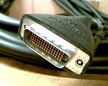
HDCI (High Definition Camera Interface) used in Polycom HDX video conferencing systems. It uses a 60-Pin Low-force helix high-density connector interface.
Provides input for the main camera and second camera. These inputs support multiple formats in a single connector (Composite, S-Video, or analog Component YPbPr) and RS232 Serial PTZ control using the Sony VISCA Protocol
Pin Outs
 1  RS232 Rx
 2  RS232 Tx
 3  IR
 4  +12 V DC
 5  +12 V DC
 7  Ground - IR RTN
 8  Ground
10  +12 V DC
11  +12 V DC
12  Pb / B Shield
13  Pb / B
14  Pr / R / C Shield  - CHROMA
15  Pr / R / C ( pg 70 of Integrators's Reference indicates 15 is Shield and 14 is Chroma for SVideo input )
16  Left Mic
17  Right Mic
18  ARM Mic
19  Center Mic
42  A Ground
43  A Ground
44  Right Mic Shield
45  Left Mic Shield
46  Y / G / C Shield
47  Y / G / C   -  LUMA
48  P Ground
50  H Sync
51  V Sync
52  H / V Shield
58  P Ground
External links
