Ionospheric pierce point: Difference between revisions
#REDIRECT Rosetta (disambiguation) Tags: New redirect Reverted Disambiguation links added |
|||
| Line 1: | Line 1: | ||
{{Short description|Article}} |
|||
#REDIRECT [[Rosetta (disambiguation)]] |
|||
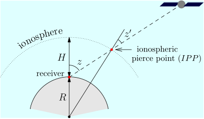
[[Image:IPP.svg|thumb|right|400px|The signal transmitted from the satellite to the receiver crosses the ionospheric shell in the so-called ''ionospheric pierce point'' (IPP). The zenith angle at |
|||
the IPP is ''z''' and the signal arrives at the receiver with zenith angle ''z''. Here ''R'' is the mean Earth radius, ''H'' is the mean height of the ionosphere shell.]] |
|||
Most [[global navigation satellite system]]s (GNSS) are subjected to errors induced by the [[ionosphere]]. Because [[ionospheric delay]] affects the speed of microwave signals differently depending on their frequency—a characteristic known as [[Dispersion (optics)|dispersion]], delays measured on two or more frequency bands can be used to measure dispersion, and this measurement can then be used to estimate the delay at each frequency. |
|||
The principal source of the dispersion comes from the [[total electron content]] (TEC) in the ionosphere, along the line of sight from the [[satellite]] to the receiver. Because it is difficult to measure the TEC along the line of sight, instead a prediction can be made using a simplified model of the ionosphere. |
|||
This model assumes that the ionosphere is a thin, uniform-density shell about the earth, located near the mean altitude ''H'' of maximum TEC (approx. 350 km). Using geometry, a slant intersection with this shell model can be determined and a vertical TEC measurement inferred. The intersection between line of sight and this shell is called the ''ionospheric pierce point'' (IPP). The perpendicular projection onto the earth's surface is called the ''subionospheric point''. |
|||
==References== |
|||
{{Reflist}} |
|||
==Sources== |
|||
* ''Satellite altimetry and earth sciences'', By Lee-Leung Fu, [[Anny Cazenave]], page 56. |
|||
==External links== |
|||
* [https://archive.today/20120803044748/http://www.kowoma.de/en/gps/errors.htm "Sources of Errors in GPS"] |
|||
[[Category:Global Positioning System]] |
|||
[[Category:Ionosphere]] |
|||
{{plasma-stub}} |
|||
{{astrophysics-stub}} |
|||
Revision as of 21:49, 24 May 2023

Most global navigation satellite systems (GNSS) are subjected to errors induced by the ionosphere. Because ionospheric delay affects the speed of microwave signals differently depending on their frequency—a characteristic known as dispersion, delays measured on two or more frequency bands can be used to measure dispersion, and this measurement can then be used to estimate the delay at each frequency.
The principal source of the dispersion comes from the total electron content (TEC) in the ionosphere, along the line of sight from the satellite to the receiver. Because it is difficult to measure the TEC along the line of sight, instead a prediction can be made using a simplified model of the ionosphere.
This model assumes that the ionosphere is a thin, uniform-density shell about the earth, located near the mean altitude H of maximum TEC (approx. 350 km). Using geometry, a slant intersection with this shell model can be determined and a vertical TEC measurement inferred. The intersection between line of sight and this shell is called the ionospheric pierce point (IPP). The perpendicular projection onto the earth's surface is called the subionospheric point.
References
Sources
- Satellite altimetry and earth sciences, By Lee-Leung Fu, Anny Cazenave, page 56.
External links
