Butterfly diagram
- This article is about butterfly diagrams in FFT algorithms; for the sunspot diagrams of the same name, see Solar cycle.

In the context of fast Fourier transform algorithms, a butterfly is a portion of the computation that combines the results of smaller discrete Fourier transforms (DFTs) into a larger DFT, or vice versa (breaking a larger DFT up into subtransforms). The name "butterfly" comes from the shape of the data-flow diagram in the radix-2 case, as described below. The same structure can also be found in the Viterbi algorithm, used for finding the most likely sequence of hidden states.
Most commonly, the term "butterfly" appears in the context of the Cooley-Tukey FFT algorithm, which recursively breaks down a DFT of composite size into smaller transforms of size where is the "radix" of the transform. These smaller DFTs are then combined with size- butterflies, which themselves are DFTs of size (performed times on corresponding outputs of the sub-transforms) pre-multiplied by roots of unity (known as twiddle factors). (This is the "decimation in time" case; one can also perform the steps in reverse, known as "decimation in frequency", where the butterflies come first and are post-multiplied by twiddle factors. See also the Cooley-Tukey FFT article.)
Radix-2 butterfly diagram
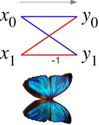
In the case of the radix-2 Cooley-Tukey algorithm, the butterfly is simply a DFT of size 2 that takes two inputs (corresponding outputs of the two sub-transforms) and gives two outputs by the formula (not including twiddle factors):
If one draws the data-flow diagram for this pair of operations, the to lines cross and resemble the wings of a butterfly, hence the name (see also the illustration at right).
More specifically, a decimation-in-time FFT algorithm on inputs with respect to a primitive -th root of unity relies on butterflies of the form:
- ,
where k is an integer depending on the part of the transform being computed. Whereas the corresponding inverse transform can mathematically be performed by replacing with (and possibly multiplying by an overall scale factor, depending on the normalization convention), one may also directly invert the butterflies:
- ,
corresponding to a decimation-in-frequency FFT algorithm.
The Butterfly DIT FFT scheme
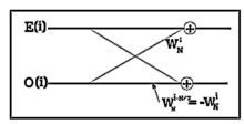
All of DFT's frequency outputs can be computed as the sum of the outputs of two length-N/2 DFTs, of the even-indexed and odd-indexed discrete-time samples, where the odd-indexed short DFT is multiplied by a so-called twiddle factor [1] term . The equation
is referred as the FFT butterfly [2] [3] operation and is graphically shown in Fig.1.

Figure 2 illustrates how the FFT algorithm works by showing the implementation of the decimation-in-time FFT. The frequency outputs of the length-N/2 DFT of the even-indexed time samples are denoted and those of the odd-indexed samples as .

Because of the periodicity with N/2 frequency samples of these length-N/2 DFTs, and can be used to compute two of the length-N DFT frequencies, namely and but with different twiddle factor . Such a reuse of these short-length DFT outputs gives the FFT its computational savings.[4]
See also
References
- ^ Gentleman, W.M.; Sande, G. (November 7–10, 1966). "Fast Fourier Transforms: for fun and profit". Proceedings of the fall joint computer conference. pp. 563–578.
{{cite conference}}: Unknown parameter|booktitle=ignored (|book-title=suggested) (help)CS1 maint: date format (link) CS1 maint: year (link) - ^ Chernenko, Serge, Fourier volume rendering on the GPU using a split-stream-FFT, retrieved 5 January 2010
- ^ Jansen, T.; von Rymon-Lipinski, B.; Hanssen, N.; Keeve, E. (2004). "Fast Fourier Transforms: for fun and profit". Vision, modeling and visualization. pp. 395--403.
{{cite conference}}: Unknown parameter|booktitle=ignored (|book-title=suggested) (help) - ^ Jones, D. (Sep 15, 2006), Decimation-in-time (DIT) Radix-2 FFT, retrieved 5 January 2010


